Within the EASITrain project, novel methods and technologies to reach a cost and energy efficient cryogenic cycle for the Future Circular Collider (FCC) have been investigated. In current state of the art cryogenic cycle, helium is often used as a coolant but its low molecular weight requires screw compressors with inherently low efficiencies. Hence, the idea of replacing standard screw compressor with the more efficient turbocompressor technology emerged. However, this approach becomes only economically viable once helium is ballasted with a heavier gas such as neon, resulting in a so-called Nelium gas mixture.
To determine the limitations and opportunities brought by radial compressor technology operating with such light gases, a closed-loop turbocompressor test facility has been designed, assembled and commissioned at the University of Stuttgart in cooperation with TU Dresden. This test rig, featuring an ultra-high speed turbocompressor directly driven by a high power density motor and supported by gas bearings, enables to measure and validate the aerodynamic performance of novel turbocompressor stages.
The compressor itself and the test rig have been designed to operate with air as well as within the whole range of Nelium mixtures, i.e from pure neon to pure helium. The geometry of three different compressor stages have been optimised numerically for aerodynamic performance while ensuring structural integrity. For this purpose, CFD simulations evaluating aerodynamic performance have been coupled to optimisation algorithms coming from the field of Machine Learning and finally FE simulations ensure that peak stresses during operation remain below material limitation.
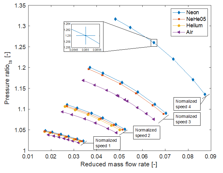
With the objective of comparing the aerodynamic performance of compressors operating with different gases, performance parameters can be normalized to account for a change in gas molecular weight. Such results acquired with the first compressor design on this test facility are shown in Figure 1 for the case of air, helium, neon and a Nelium mixture. From these results, correlations can be derived to predict the performance variation when changing from one operating gas to another.
The first compressor was developed as an exploratory design allowing for wide variations of mass flow rate, rotational speed and operating gas properties. As depicted in Figure 2 with a cross section of Rotor #1, the flow enters the machine axially, goes through the impeller followed by an unbladed diffuser and finally the volute. All of these features make this compressor stage the ideal test case for the commissioning of an experimental test stand as well as to acquire knowledge on the effect of operating with gases of various molecular weights, including very light ones such as helium.
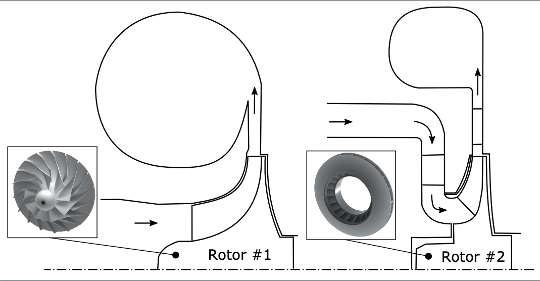
The second design, on the other hand, was developed following different specifications. The objective was to obtain a compressor compact enough to fit into a multi-stage compressor machine featuring several stages stacked one behind each other in order to achieve the desired overall pressure rise. Additional constraints to an operation in a multi-stage machine was also added such as the requirement of entering radially into the stage or having a rotating cover disk on the blades tip resulting in a so-called shrouded impeller. Since one of the main challenges when compressing light gases is achieving a high pressure rise, a stringent target for the desired pressure ratio was also set. Figure 2 illustrates the difference between the two geometries visualised in a meridional plane for both stages.
This second compressor stage is currently in the process of being manufactured using different processes including 5-axis machining, electro-erosion and prototype casting. In various stages of the design, additive manufacturing was also employed for prototyping.