The FCC-ee project envisions a double-ring lepton collider in a new tunnel with a circumference of 91 km that will achieve the necessary conditions for the discovery of new physical phenomena beyond the frontier established by the standard model. An ongoing feasibility study, coordinated by CERN and supported through the H2020 FCCIS project, explores different concepts for the sustainable and efficient construction and operation of this machine. The FCC-ee will be implemented in stages as an electroweak, flavour, Higgs, and top factory by spanning the energy range from the Z pole and the WW threshold through the maximum Higgs production rate, up to the top threshold and beyond.
The biggest motivation for using Combined Function Magnets (CFM) in an optics design for the FCC-ee is the decrease of the synchrotron radiation power in the beams of FCC-ee. Consequently, this would result in energy savings during the FCC-ee runs. It should be noted that synchrotron radiation power scales as the energy to the fourth power and is inversely proportional to the bending radius of the accelerator.
In the proposed CFM, a quadrupolar magnetic component is superimposed on a dipolar one, thereby increasing the so-called Filling Factor (FF), defined as the percentage of the accelerator filled by dipole magnets and increasing the bending radius. CFMs have been previously used in many particle accelerators such as the Proton Synchrotron (PS) at CERN, the Alternating Gradient Synchrotron (AGS) at the Brookhaven National Laboratory in USA and the ALBA in Spain. Traditionally the arc dipoles are provided with a quadrupolar field to reduce the length required by quadrupole magnets, but for the FCC-ee the original proposal was to use an innovative design based on High Temperature Superconductors (HTS) to replace the lattice quadrupoles with CFMs, using normal conducting magnets for the arc dipoles with only dipolar field. However the proposed optics solution presented in the following could also be studied for normal conducting CFMs.
In a first approach, the total bending angle corresponding to the sum of the four dipoles per FODO cell (B1) in the Z-lattice was distributed between the four dipoles and the two new CFMs with quadrupolar components (Bf and Bd). By “FODO" lattice we refer to the periodic sequence of focusing and defocusing quadrupole magnets, with dipole magnets or drift spaces between them -denoted by "O".
Implementing an equal dipolar magnetic field in the quadrupoles of the FODO lattice for the Z run of FCC-ee results in an unstable lattice due to the increased synchrotron in these quadrupoles. Therefore schemes unbalancing the strength of the dipolar fields in the two quadrupoles had to be explored. A sketch of the lattices for the Z and tt runs of FCC-ee is given in Fig 1, where the main dipoles are labeled as B1, and the quadrupoles as QF and QD. For the CFM, Bf and Bd represent the dipolar component.
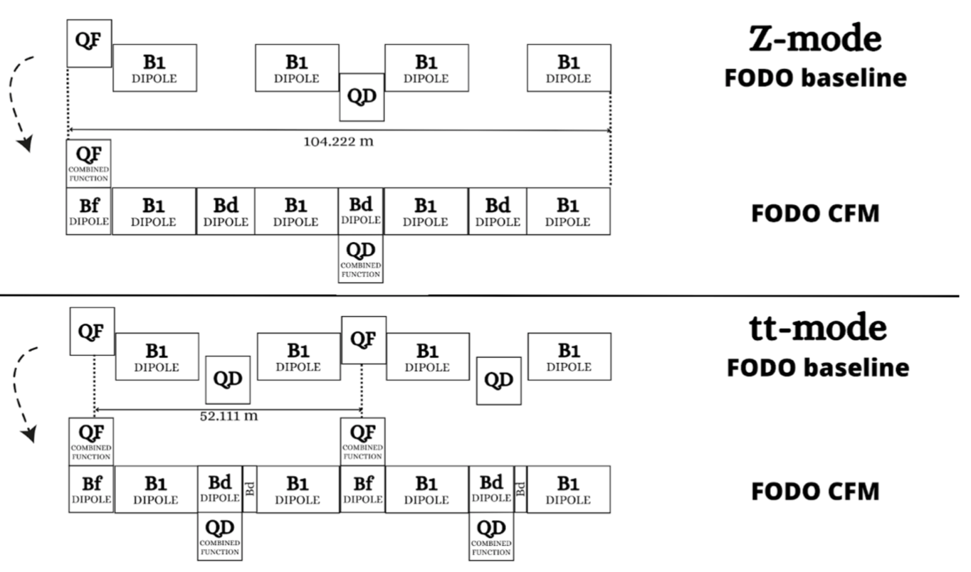
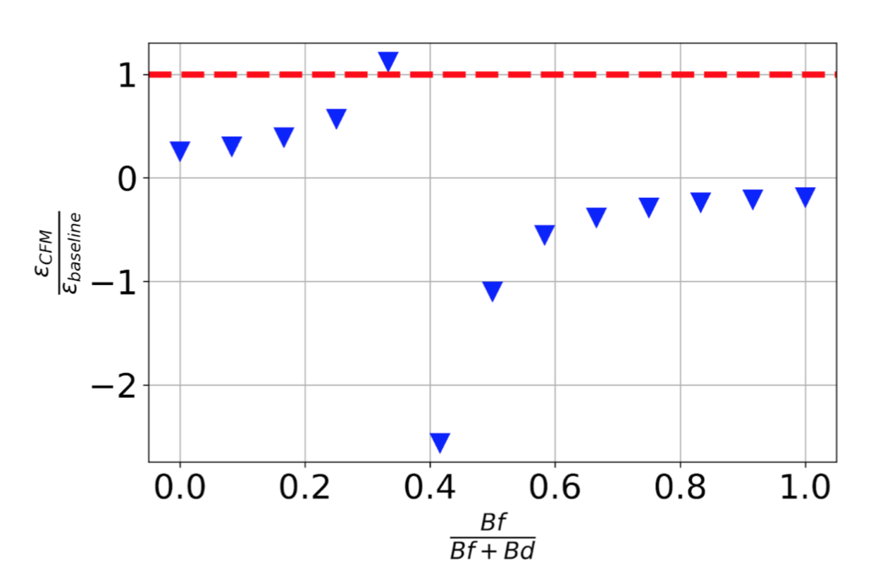
Figure 2 shows the equilibrium beam emittance for the Z lattice as a function of the ratio Bf/(Bf+Bd), while keeping Bf+Bd constant for this scan. Above a ratio of 0.4 the equilibrium emittance is negative, implying an unstable solution. To achieve the baseline equilibrium emittance for a FODO cell and similar partition numbers, the ratio between Bf/(Bf+Bd) is about ⅓.
The required magnetic fields for the baseline and CFM cells are shown in Table 1. The present solution has a larger dipole field in the defocusing CFM than in the main dipole (B1) but this ratio could be optimized easily for global performance or magnet design constraints.
| Magnetic field & gradient | Baseline | CFM | Length [m] |
|---|---|---|---|
| B1 | 0.0137 T | 0.0108 T | 22.65 |
| Bf | 0 | 0.0075 T | 2.9 |
| Bd | 0 | 0.0151 T | 2.9 / 3.9 |
| Quad F | 1.306 T/m | 2.9 | |
| Quad D | -1.306 T/m | 2.9 | |
Table 1: Magnetic strengths for the baseline and CFM cells of the Z mode. Note that the B1 field in the nominal configuration corresponds to the longer arc dipole in the FCC-ee lattice.
The twin quadrupole magnets for the e+ and e- apertures have opposite polarity. In the CFM cell this implies a different bending angle for the two counter-rotating beams at the location of the quadrupoles (Bf and Bd), resulting in slight differences in the layouts. This should be carefully evaluated and taken into account for the final ring and magnet designs. Similarly the compatibility between Z and tt layouts using these CFMs should be studied.
In terms of energy savings, the synchrotron radiation power in this CFM lattice is about 17% lower than in the baseline for the Z-mode which corresponds to a saving of about 17 MW in the RF cavities. The magnet power consumption should also be reviewed for HTS and normal conducting options to have a final estimate of total power reduction with respect to the present baseline.
In summary, optics developments with CFMs in the arc quadrupole locations are showing promising results to improve the FCC-ee performance and efficiency.
___________________________________________________________________
FCC-ee HTS4 and FCC-ee Beam Dynamics projects are supported by the Swiss Accelerator Research and Technology (CHART).
This project has received funding from the European Union’s Horizon 2020 research and innovation programme under the Marie Skłodowska-Curie grant agreement No. 945363, EPFLglobaLeaders.